This article describes how to implement colour deconvolution and un-mixing method for RGB images in arivis Vision4D.
Introduction
Colour or RGB images are common in histopathology where bright-field images capture white light from which the diagnostic dyes absorb a certain portion of the spectrum. These images can be segmented in a range of ways, but a better separation of the signal components from the red, green, and blue channels can significantly improve segmentation results. This script is an implementation in Vision4D of the method developed by Ruifrok, A.C. & Johnston, D.A. as described here.
This method has been developed specifically for the unmixing of diaminobenzidine, hematoxylin and eosin dies.
The output of the script is the creation of three additional channels to the current image set containing the unmixed signal.
This script relies on the NumPy libraries that are installed automatically with version 3.4 or above of arivis Vision4D. Earlier versions may require additional components.
Importing and editing the script
The script can be downloaded here. Once the ZIP file is decompressed the PY file can be loaded into the script editor.
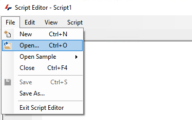
Once opened the script will probably require some modifications for each specific usage.
RGB Color Mapping
By default, color images are imported so that the first channel is red, the second channel is green and the third channel is blue. However, images imported from other formats may end up being imported with the channel order reversed. Modifying the channel colors in the viewer is easy enough, we simply need to right-click on the channel gradient and select a new color,
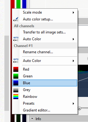
but the channel order cannot be modified and this must must be accounted for in the script settings.
In the script editor, under the User Settings section, you will find entries for defining the channel number for each color. Note that the first channel is channel 0. In the example below the first channel is red, the second is green, and the third is blue.
# @@@@@@@@@@@@@@@@@@@@@@@@@@@@@@ USER SETTINGS @@@@@@@@@@@@@@@@@@@@@@@@@@@@@@@@
#
# -----------------------------------------------------------------------------
# Skeleton section - Script
# INPUT_CHANNEL channel with the binary image
#      is only used to read/write the voxels
# ---> imageset.get_channeldata / imageset.set_channeldata
# -----------------------------------------------------------------------------
INPUT_CHANNEL_R = 0
INPUT_CHANNEL_G = 1
INPUT_CHANNEL_B = 2
Simply type in the correct numbers for each as required.
Dye Selection
The script has been preconfigured for specific dye combinations. For the un-mixing to work, the correct combination must be selected. Immediately below the Input Channel settings, you'll find the STAINING settings.
# -------------------------------------------------------------------------
# 0 == HEMA_DAB
# 1 == HEMA_EOSIN
# 2 == HEMA_EOSIN2
# 3 == FEULGEN_LGRENN
# 4 == HEMA_EOSIN_DAB
# 5 == GIEMSA
# 6 == Fast Red, Fast Blue and DAB
# 7 == Methyl green and DAB
# 8 == Haematoxylin, Eosin and DAB (H&E DAB)
# 9 == Haematoxylin and AEC (H AEC)
# 10 == Azan-Mallory
# 11 == Alcian blue & Haematoxylin
# 12 == MASSON THRICROME
# 13 == Haematoxylin and Periodic Acid of Schiff (PAS)
# -------------------------------------------------------------------------
STAINING = 0
Simply replace the number after the "STAINING = " to match your image. For example, if using Hematoxylin and Eosin (H&E), the line should then read:
STAINING = 1
Inverting the Output
Brightfield color imaging is a subtractive process where we start with white light and the dyes absorb various components of the white spectrum. The unmixing method generates images that are white with the dye reducing the signal to 0 (black/dark signal on white background). However, many segmentation methods in arivis Vision4D were implemented with fluorescence in mind as a default where the background is typically dark and the signal is a positive deviation from that (white/channel color on black background). This script has been implemented with an option to invert the output to make segmentation easier. If you want to invert the output so that the signal is bright on a dark background, you can simply change the following line:
# -----------------------------------------------------------------------------
INVERT_IMAGE = False
to
# -----------------------------------------------------------------------------
INVERT_IMAGE = True
Applying the script to an image
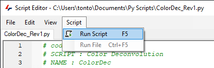
Once all the necessary edits have been made we can run the script on an image. If the script editor is still open, the script can be run by clicking on Script>Run Script or by pressing the F5 key on the keyboard.
Note that the script will run on the active image set. If more sets need to be processed, you can select these additional sets in the viewer and run the script again or modifying the script to process multiple sets.
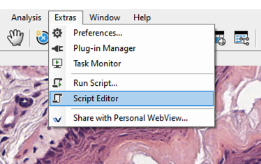
The script can also be run directly from the Vision4D window by going to Extras> Run Script... and selecting the .py file that has been saved after making the necessary changes described above.
Interpreting the results
The output of the script is three additional channels in the source image sets. These channels are named for the dye signal that has been extracted and can be used in any pipeline as any regular image channel for segmentation etc. In cases of dual staining (e.g. H&E), the third channel essentially contains only the signal that could not be reliably attached to either of the other two. this means that this third channel can essentially be used as some form of quality control for the output since in a perfect deconvolution this third channel would ideally be empty. If there is still a strong signal in the third channel this usually indicates that the deconvolution parameters do not perfectly match the staining in the image. This could be caused by white balancing issues or extreme staining (either too weak or too strong).
For more information on the process of the deconvolution, please refer to the published literature on which this is based, linked above.
Conclusions
Once the script has been run, pipelines can be created as per usual that can use the newly created channel for segmentation or any additional modification, just like any other image channel.
Support for this script can be obtained by logging a support ticket using the link at the top of this page.
A more detailed description of the script functionality and editing can be found here.
Download the script
Download the script for arivis Vision4D 3.3/3.4 here (may work with earlier versions but has been tested in 3.3 and 3.4).
Download the script for version 3.5 and above here.